Configure Cisco dhcp relay agents using packet tracer in two minutes
In this lab, I will share with us on how to configure Cisco dhcp relay agents using Packet Tracer. Configuring dhcp relay agents helps to reduce the number of dhcp servers on your networks, making the task of IP address mangement less complicated.
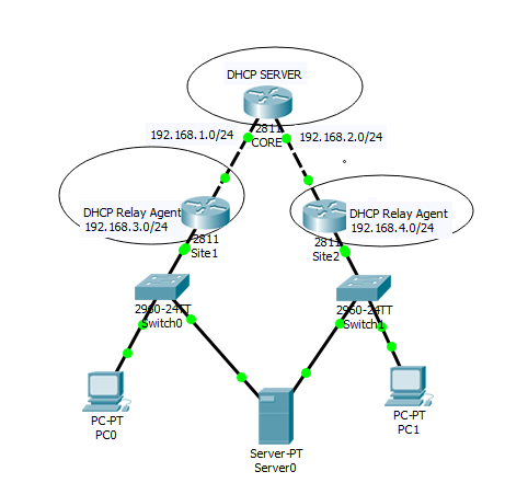
For this lab, my core router is going to be configured to serve as a dhcp server to the two local area networks attached to site1 and site2 routers. Site1 and Site2 routers will be configured as Cisco dhcp relay agents. Their job is to help take dhcp requests from hosts to the dhcp server and deliver IP addresses from the dhcp server to hosts. But wait a minute, why can’t we just configure Site1 and Site2 routers as dhcp servers to the hosts behind them instead of provisioning them as Cisco dhcp relay agents? Well, you can, but that will mean having multiple dhcp servers as your network grows and that could make the job of IP management a complex task.
The task is simple with very minimal configuration commands but must be done carefully, considering that Site1 and Site2 LAN hosts are not directly connected to the core router. Let’s look at the network topology below before we proceed.
Network topology

I will start by configuring the Core. The following tasks will be performed on the Core router:
- Configure the two interfaces connecting to Site1 and Site2 routers with IP addresses 192.68.1.1/30 and 192.168.2.1/30 respectively.
- Configure dhcp servers for networks 192.168.3.0/24 and 192.168.4.0/24, even though they are not directly connected to the Core.
- Configure static route to reach networks 192.168.3.0/24 and 192.168.4.0/24
You may also like: How to configure multiple dhcp for different vlans in Cisco Packet Tracer
Core router configuration:
Core(config)#interface FastEthernet0/0
Core(config-if)#ip address 192.168.1.1 255.255.255.252
Core(config-if)#no shut
Core(config-if)#interface FastEthernet0/1
Core(config-if)#ip address 192.168.2.1 255.255.255.252
Core(config-if)#no shut
Core(config)#ip route 192.168.3.0 255.255.255.0 192.168.1.2
Core(config)#ip route 192.168.4.0 255.255.255.0 192.168.2.2
Core(config)#ip dhcp pool Site1
Core(dhcp-config)#network 192.168.3.0 255.255.255.0
Core(dhcp-config)#default-router 192.168.3.1
Core(dhcp-config)#dns-server 192.168.3.1
Core(dhcp-config)#ip dhcp pool Site2
Core(dhcp-config)#network 192.168.4.0 255.255.255.0
Core(dhcp-config)#default-router 192.168.4.1
Core(dhcp-config)#dns-server 192.168.4.1
Core(dhcp-config)#exit
Core(config)#ip dhcp excluded-address 192.168.3.1
Core(config)#ip dhcp excluded-address 192.168.3.255
Core(config)#ip dhcp excluded-address 192.168.4.255
Core(config)#ip dhcp excluded-address 192.168.4.1
Configuring Cisco dhcp relay agent on Site1 and Site2 Routers.
Site1 router
Site1(config)#interface FastEthernet0/0
Site1(config-if)#ip address 192.168.1.2 255.255.255.252
Site1(config-if)#desc connection to Core
Site1(config-if)#no shut
Site1(config-if)#interface FastEthernet0/1
Site1(config-if)#ip address 192.168.3.1 255.255.255.0
Site1(config-if)#desc connection to LAN
Site1(config-if)#ip helper-address 192.168.1.1
Site1(config-if)#no shut
Site2 router
Site2(config)#interface FastEthernet0/0
Site2(config-if)#ip address 192.168.2.2 255.255.255.252
Site2(config-if)#desc connection to Core
Site2(config-if)#no shut
Site2(config-if)#interface FastEthernet0/1
Site2(config-if)#ip address 192.168.4.1 255.255.255.0
Site2(config-if)#desc connection to LAN
Site2(config-if)#ip helper-address 192.168.2.1
Site2(config-if)#no shut
Verification
To verify that the lab is working as intended, we simply go to the PCs and set the network adapter to acquire IP automatically. See results below:

From the image above, you can see that while PC0 acquired its IP from the dhcp server configured for subnet 192.168.3.0/24, PC1 acquired its IP from the dhcp server configured for subnet 192.168.4.0/24. The reason for this is obvious- they are on different networks and are being serviced by different dhcp relay agents that were confiured for different dhcp pools. As for the server shown in the topology, the two ethernet adapters will acquire IP addresses from both LAN subnets. It is designed for fault-tolerance.
If you enjoyed this tutorial, please subscribe to this blog to receive my posts via email. Also subscibe to my YouTube channel, like my Facebook page and follow me on Twitter. To get the Packet Tracer file for this lab, simply drop your email address in the comment section of this blog.
Tidak ada komentar:
Posting Komentar